
![]()

grant agreement n° 714235
The remarkable progress in experimental physics in the last decade has enabled scientists to manipulate, control and detect the state of various quantum systems to a high degree. These efforts were in part motivated by quantum information processing applications (QIP) – where the goal is to build a quantum computer - and the desire to understand the interactions in many-body systems on a fundamental level. This research, and the necessary development of new tools, has already led to applications relying on quantum systems such as: the enhancement of state detection via entanglement in a frequency standard, the use of qubits for quantum repeaters, secure quantum enhanced communication protocols and tests of quantum theory in multi-qubit systems.
Yet, the realization of a universal quantum computer has proven to be a very demanding goal for experiments. As a consequence the focus has shifted to using controllable quantum systems to investigate specific quantum phenomena. The idea is to build a device that mimics a quantum system whose dynamics is either very hard to or cannot be simulated in a relevant timescale with a classical computer. Compared to a universal quantum computer such a device could be much easier to realize and less prone to errors, as one is typically not interested in a faithful representation of the full many-body wave function.
One of the most intensively studied system in the context of quantum simulation are interacting spins which can be used as a model to describe a wide range of quantum systems. While there has been a steady progress in simulating the physics of 1D spin chains, extending these remarkable experiments beyond the one dimensional chain is still an open experimental challenge. In particular, the precise control over the state dynamics and access to the relevant observables required to study quantum phenomena in detail remains particularly difficult.
The aim of this project is to experimentally implement a platform for analog quantum simulation of interacting spin models arranged in one and two-dimensional geometries. The scheme capitalizes on the remarkable recent developments in circuit Quantum Electro Dynamics (cQED), especially the 3D transmon qubit. The central idea behind this work is to exploit naturally occurring dipolar interactions between two superconducting 3D transmon qubits to engineer the desired spin-spin interactions. For the two qubit interaction we choose to use the pairwise spin-spin coupling where the strength depends on the distance and respective angles of the qubits. This interaction is three to four orders of magnitude larger than the decoherence rates for typical 3D transmon qubits and will dominate the properties of the system. Combining this interaction with the ability to arrange the qubits on essentially arbitrary geometries paves the way to the realization of a broad class of dipolar spin models ranging from linear spin chains to ladder geometries (see Fig. 1). Together with Peter Zoller and his group, we have developed a scheme that promises a faithful implementation of many-body spin-1/2 Hamiltonians involving tens of qubits [1]. Currently we are implementing and investigating the tools and methods required to build such a system.
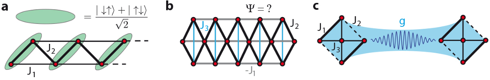
Fig. 1: Examples for quantum simulation problems to be realized within this project. Red discs stand for spins/qubits, solid lines for spin-spin interactions Ji and the blue area for a photon mediated interaction. (a) Sketch of a dimerized phase of the extended XY model on a triangular ladder. For J2/J1=0.5 the phase can be understood as a solid of local triplet states, denoted by the green shaded areas. (b) Example of a two-dimensional triangular lattice configuration highlighting the flexibility of this approach. The values of Ji can be adjusted over a wide range from positive to negative interactions. Such a system, when scaled beyond 20 qubits, is very hard to simulate classically. (c) With the methods and tools available in the experiment we can realize a system where multiple spins interact locally with a dipole-dipole interaction J and couple to another identical system with a long range photon mediated coupling g. This will allow us to study open system dynamics with interacting spin systems
With the aim to realize an analog quantum simulator to study complex spin models such as the XY-model (Fig. 1a), we studied the required building blocks for such experiments in detail. In particular, we are currently establishing protocols and methods to precisely initialize the ground state of the system, control the interactions and readout single qubit states and multi-qubit correlations.
Dipole-dipole interactions of superconducting qubits
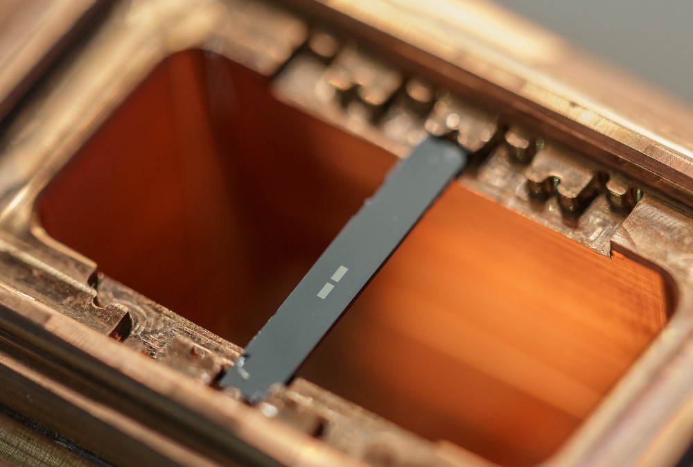
Fig. 2: Photograph of one half of a 3D circuit QED setup. The cavity is made out of copper. In the centre of the cavity rests a piece of silicon with a single 3D transmon qubit on top. The grey structure visible ontop of the piece of silicon is the aluminium antenna of the 3D transmon which forms the necessary shunting capacitance and couples the qubit to the cavity or another qubit close to it.
The fundamental building block for our approach is the 3D transmon. A transmon qubit is realized by shunting a Josephson junction with a large capacitance as shown in Fig. 2. Due to the non-linearity of the Josephson junction this effectively creates an anharmonic oscillator with a level spacing in the 5-10 GHz regime and an anharmonicity of about 200 - 300 MHz. Within this anharmonic potential, we can use the lowest two energy levels to realize a qubit.
We have performed [1] a feasibility study to build an analog quantum simulation system using the 3D circuit QED architecture. The central feature of our approach is the design flexibility in the inter-qubit interaction which results from the dipole-antenna structure of the 3D transmon. As one can expect, two dipole-antennas in the near field interact like two spins. We have studied this behaviour theoretically by using finite element simulations and comparing them to a lumped element model of the qubit. By designing the shape and size of the antenna we expect to be able to realize large interaction strengths (Ji,j=2 = 100 MHz) at inter-qubit distances of a few mm (see Fig. 3). The interaction between the qubits ultimately comes from an effective capacitance between the antennas with an angle and distance dependence closely matching the behaviour expected from dipoles. As a result, the system dynamics of two capacitively interacting 3D transmons, is described by a generalized XY Hamiltonian with a 1/r³ distance dependence.
The key element of our implementation is the realization of different patterns which lead to quantum frustration by tuning the form of the interaction couplings Ji,j (Fig. 3). The coupling can be modelled by a typical dipole-dipole interaction and a small, constant cavity mediated term Jcav. These couplings display a rich dependence as a function of the dipole angles (Fig. 3b). This dependence is essential to tune the coupling between different spins from positive to negative, or to (approximately) set it to 0. Even more crucially, the 1/r3 dependence (see Fig. 3a) can be exploited to further modify the magnitudes of the couplings. Different geometries can be quickly implemented by either fabricating a new chip or physically moving the qubit location.
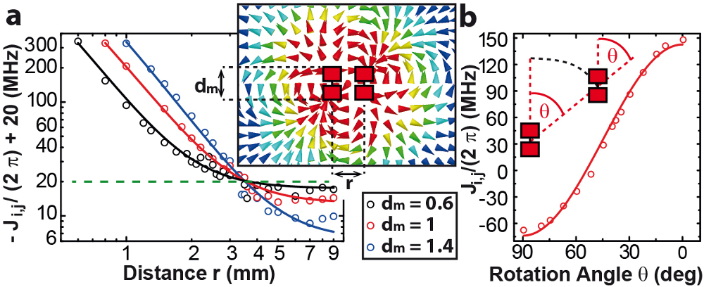
Fig. 3: Microscopic finite-element simulation of the dependence of the coupling Ji,j between two qubits. (a) Distance dependence on the coupling Ji,j for three different antenna length dm (given in mm). The dashed line indicates Ji,j = 0. The inset displays a typical result from finite element simulations, with the dipole antennas surrounded by the computed electric field (intensity decreasing from red to blue). (b) Angular dependence illustrated for the case Θi = Θj = Θ at a distance r = 1.5mm. The solid lines show the expected qubit-qubit coupling assuming a dipole like interaction.
A schematic illustration of a setup for simulating an XY model on a ladder can be seen in Fig. 4. The transmon qubits can be fabricated in an essentially arbitrary lattice configuration with locally controllable orientation. The 3D cavity around the qubits is used to readout and drive a subset of qubits, providing means for both adiabatic state preparation and probing. The cavity can be made out of copper to be able to easily apply magnetic fields from the outside, or aluminium to achieve the highest quality factors. The coupling to the cavity and thus the readout and driving can be adjusted by rotating the qubits inside the cavity. The qubit cavity coupling will be determined by the overlap of the qubits dipole moment, which is aligned with the long axes of the qubit, and the electric field in the cavity.
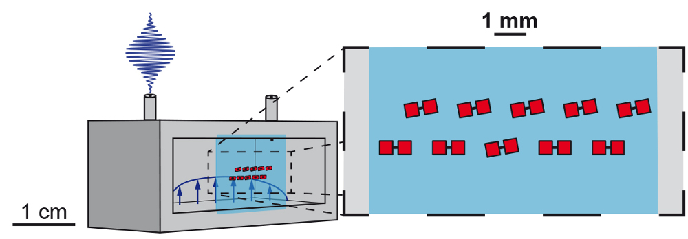
Fig. 4: Conceptual schematic of how to realize a frustrated XY spin ladder using a cQED setup. The drawing shows one half of a 3D cavity with two microwave couplers. Inside the cavity (grey) is a piece of sapphire (light blue) with multiple transmon qubits (red) arranged on a triangular ladder. The rotation angles of the qubits are chosen such that they couple strongly to each other but only the ones which are not horizontal couple to the cavity mode.
Fast flux tuning of 3D transmon qubits
An important feature in investigating different lattice configurations is the possibility to change the frequency of SQUID-based transmon qubits by applying magnetic flux. Such tunability allows to controllably tune certain qubits into resonance, which enables the exchange of photons between them. In the same way, qubits can also be detuned from each other to avoid any energy exchange. When the tunability is fast enough - faster than the qubits’ decoherence time and their coupling rate – it is then possible to investigate quench dynamics and to individually read out the state of single qubits in the lattice.
Implementing fast flux control on a SQUID-based transmon qubit remains challenging in the three dimensional cavity architectures due to the presence of a massive metallic cavity. Indeed, the simplest option of putting a coil outside a copper cavity suffers from counteracting eddy currents in the cavity wall. Another option is provided by flux bias lines as has been implemented in planar structures, which are micrometer sized U-shaped wires. Unfortunately, in the 3D architecture this requires a loop entering the cavity, leading to enhanced cavity and qubit decay.
Here, we introduce a magnetic hose similar to the one jointly proposed by external collaborators and the Quantum Nanophysics, Optics and Information group at the IQOQI. This hose guides a fast flux pulse from the outside to the inside of a microwave cavity. The working principle of a magnetic hose is based on two ingredients, a ferromagnetic material, which attracts magnetic field lines and a diamagnetic material, which expels magnetic field lines. For the transmission of high frequency magnetic fields, it is essential to add a slit, which prevents eddy or supercurrents (see Fig. 5).
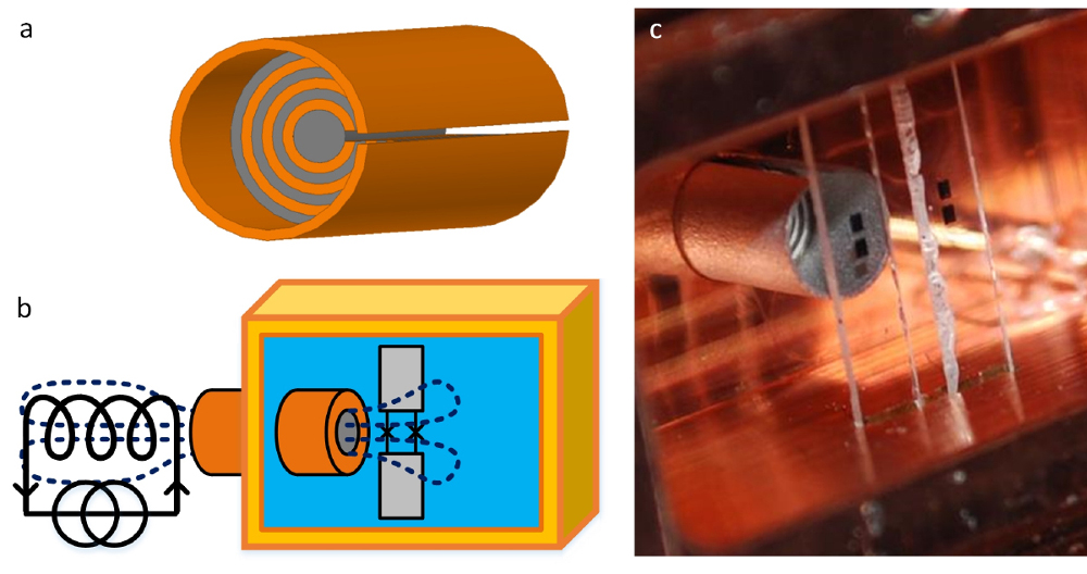
Fig. 5: (a) Design of a magnetic hose for high frequency magnetic fields. The magnetic hose consists of alternating layers of mu-metal (grey) and aluminium (orange). The slit avoids the creation of conducting loops around the transported field’s direction, hence prohibiting the appearance of counteracting currents. (b) Sketch of the setup. A coil outside the cavity generates a fast flux pulse. The fast flux pulse is guided through the hose into the cavity to the SQUID-based transmon. The magnetic field lines inside the superconducting cavity spread out like a fountain and leave again through the cavity hose, such that there is net zero flux being guided through the hose. (c) Experimental setup. Two flux-sensitive qubits and a magnetic hose are placed inside a cavity made out of copper.
The setup for a first experiment is sketched in Fig. 5b. A magnetic field is generated by a coil outside the cavity and guided by a magnetic hose through the highly conductive cavity wall to the qubit inside. First experiments using copper and aluminium cavities with two qubits inside show promising results. The transition frequency can be tuned with a simple square pulse of about 200 nanoseconds, which is much faster than the typical qubit decoherence (see Fig.6).
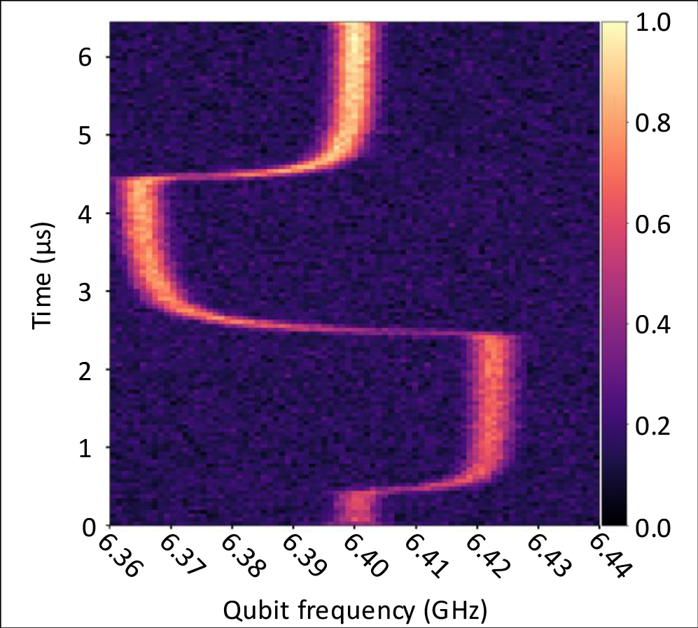
Fig. 6: Spectroscopy of a SQUID-based transmon qubit inside a waveguide cavity made out of aluminium, when applying a fast double flux pulse. The double flux pulse of 4 µs total duration is applied at t = 0.5 µs to the qubit. The spectroscopy-pulse is delayed in 50 ns increments to track the frequency of the qubit during the applied flux pulse. One can clearly observe the fast jumps and plateaus corresponding to the applied flux values.
Waveguide circuit electro dynamics
While the use of a cavity for 3D transmon qubits constitutes a promising platform to study/simulate complex spin models, its size and lack of flexibility limits the number of qubits to about ten. More importantly, by using a cavity the qubit state as well as the correlations functions can be challenging to measure. To address this problem, the cavity can be replaced by a three dimensional waveguide. Similarly to the cavity, direct coupling between qubits constitute short distance interactions and long range interactions can be mediated via photons across the waveguide. In addition, such a system allows to study dissipative coupling to an open system. Furthermore, in a 3D waveguide approach the readout of the qubits can be mediated and controlled by adding a resonator in the waveguide. For such readout, it is desirable for the qubit to be efficiently coupled to the resonator without introducing losses to the environment.
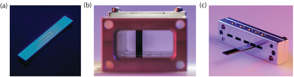
Fig.7: (a) Picture of an aluminium microstrip resonator fabricated on a silicon substrate. (b) Picture of the microstrip resonator in the aluminium waveguide. (c) Microstrip resonator mounted in the sample holder to place the sample in the aluminium waveguide
In [2], we demonstrate the experimental implementation of a 3D waveguide with a U-shaped microstrip resonators (see Fig. 7). The compact design of the resonator allows flexible coupling to the waveguide, which depends on its position within the waveguide. This approach combines a planar design with the low-loss advantages of three dimensions. As a result, in the low temperature/low energy limit we measured an internal quality factor of up to one million, a value comparable with state-of-the-art systems that are often more sophisticated.
Fig. 8 shows a conceptual schematic to experimentally realize an analog quantum simulation of a spin lattice using a microstrip resonators for the readout for the qubit state. Here, the coupling between the waveguide mode and the qubit is controlled via the orientation of the qubit. When the qubit is oriented along the waveguide axis (see Fig. 8), the coupling to the waveguide is negligible, whereas the qubit-qubit coupling is large. This geometry allows for the use of a very large number of qubits, only limited by the available physical space in the dilution refrigerator. In addition to the qubits, we will place microstrip resonators in the waveguide (black U-shaped structures) and use them for a dispersive readout of selected qubits. These resonators will provide means for locally probing the excitations and correlations in a spin chain or ladder geometry. In addition, this architecture also offers a built in protection against qubit decay mediated through the resonator i.e. Purcell effect.
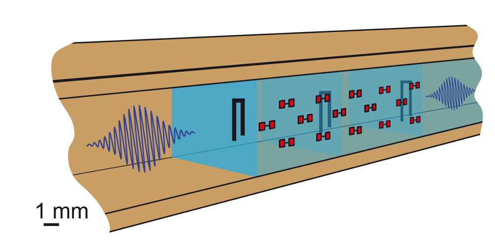
Fig. 8: A lattice of transmon qubits (red) and three microstrip resonators (black) within a waveguide for analog quantum simulation. The qubits are oriented along the propagation direction and thus have a negligible coupling to the waveguide, but are strongly coupled to each other. Using the resonators, with a slightly different resonance frequency, the readout can be performed on selected qubits.
As a first step towards complex spin models, we performed an experiment to study the interactions between 2 qubits mediated by direct dipole-dipole interactions. Both qubits are frequency tuneable using an external coil and can be brought into resonance with each other.
A typical measurement curve can be seen in Fig. 9 clearly showing the avoided crossing as the 2 quits are tuned into resonance. Here, the strength of the dipole-dipole interaction sets the splitting. On resonance, both qubits hybridize with each other resulting in sub-radiant and super-radiant states. This effect can be seen in the increased linewidth for the upper branch in the avoided crossing, indicating an increased coupling to the waveguide and a vanishing coupling for the lower branch which essentially does not interact with the waveguide. Measuring and controlling this direct dipole-dipole coupling constitute an important building block to extend this work and engineer larger systems to look into quantum simulation of many body problems.
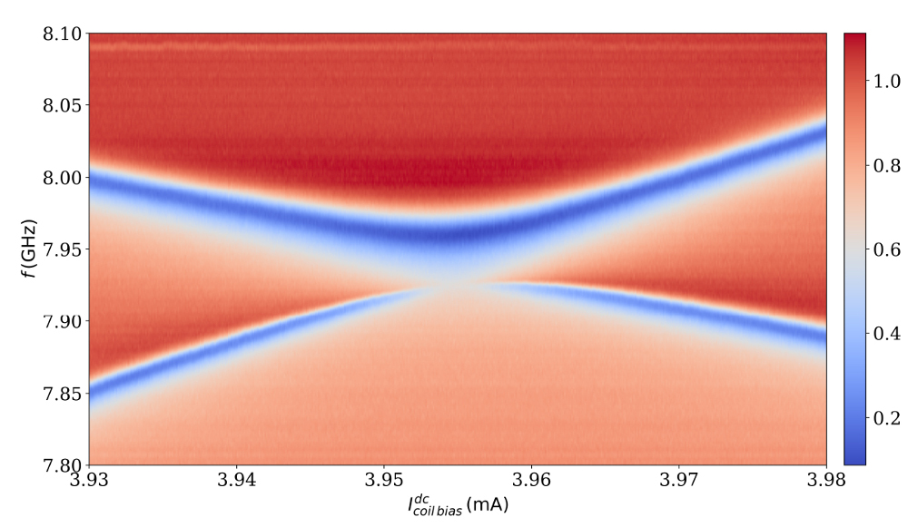
Fig. 9: Transmission measurement for two superconducting qubits coupled to a waveguide close to the avoided crossing. At resonance one can clearly observe the vanishing linewidth of the sub-radiant state and the increased linewidth of the superradiant state.
[1] Dipolar Spin Models with Arrays of Superconducting Qubits
M. Dalmonte, S. Mirzaei, P. R. Muppalla, D. Marcos, P. Zoller, G. Kirchmair
Phys. Rev. B 92, 174507 (2015)
[2] Characterization of low loss microstrip resonators as a building block for circuit QED in a 3D waveguide
D. Zoepfl, P. R. Muppalla, C. M. F. Schneider, S. Kasemann, S. Partel, G. Kirchmair
AIP Advances 7, 085118 (2017)